Gate Valve Drawing Symbol . What is a piping & instrumentation diagram (p&id)? In each process and instrumentation diagram, valves have specific symbols that make them easy to recognize. While there is some variation, examples of the standard symbols for control valves are in the pdf below. Each p&id has its own legend that identifies the symbols for the various equipment. The piping and instrumentation diagram (p& id) symbol of the gate valve is achieved by the insertion of a vertical line in between two triangles. What are valve symbols and how are they used? From the above section showing the different valve. Many types of valves are required in a process plant for flow regulation or on/off purpose. The gate valve symbol is represented by a thick line drawn straight through the middle of the centre where the two triangles meet. Type of valve employed depends on nature of fluid, flow control required,.
from fittertraining.com
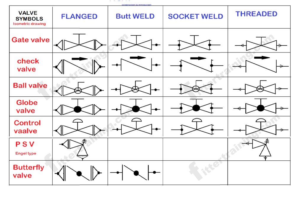
In each process and instrumentation diagram, valves have specific symbols that make them easy to recognize. Each p&id has its own legend that identifies the symbols for the various equipment. What is a piping & instrumentation diagram (p&id)? From the above section showing the different valve. The piping and instrumentation diagram (p& id) symbol of the gate valve is achieved by the insertion of a vertical line in between two triangles. The gate valve symbol is represented by a thick line drawn straight through the middle of the centre where the two triangles meet. What are valve symbols and how are they used? Many types of valves are required in a process plant for flow regulation or on/off purpose. Type of valve employed depends on nature of fluid, flow control required,. While there is some variation, examples of the standard symbols for control valves are in the pdf below.
How many types of piping valve piping valve drawing symbols Fitter
Gate Valve Drawing Symbol What is a piping & instrumentation diagram (p&id)? The piping and instrumentation diagram (p& id) symbol of the gate valve is achieved by the insertion of a vertical line in between two triangles. From the above section showing the different valve. Many types of valves are required in a process plant for flow regulation or on/off purpose. The gate valve symbol is represented by a thick line drawn straight through the middle of the centre where the two triangles meet. What is a piping & instrumentation diagram (p&id)? While there is some variation, examples of the standard symbols for control valves are in the pdf below. Each p&id has its own legend that identifies the symbols for the various equipment. In each process and instrumentation diagram, valves have specific symbols that make them easy to recognize. Type of valve employed depends on nature of fluid, flow control required,. What are valve symbols and how are they used?
From pneumaticsdirect.co.uk
1" SW 800 GATE VALVE HAND WHEEL OP Pneumatics Direct Gate Valve Drawing Symbol Type of valve employed depends on nature of fluid, flow control required,. Each p&id has its own legend that identifies the symbols for the various equipment. What are valve symbols and how are they used? What is a piping & instrumentation diagram (p&id)? The gate valve symbol is represented by a thick line drawn straight through the middle of the. Gate Valve Drawing Symbol.
From hardhatengineer.com
Valve Symbols in P&ID Ball Valve, Relief Valve and more Gate Valve Drawing Symbol From the above section showing the different valve. What are valve symbols and how are they used? In each process and instrumentation diagram, valves have specific symbols that make them easy to recognize. The piping and instrumentation diagram (p& id) symbol of the gate valve is achieved by the insertion of a vertical line in between two triangles. While there. Gate Valve Drawing Symbol.
From www.aiophotoz.com
Valve Symbols Autocad Free Cad Block Symbols And Cad Drawing Images Gate Valve Drawing Symbol What are valve symbols and how are they used? What is a piping & instrumentation diagram (p&id)? Each p&id has its own legend that identifies the symbols for the various equipment. While there is some variation, examples of the standard symbols for control valves are in the pdf below. Type of valve employed depends on nature of fluid, flow control. Gate Valve Drawing Symbol.
From engineeringdiscoveries.com
Types Of Valves, Their Functions And Symbols Engineering Discoveries Gate Valve Drawing Symbol In each process and instrumentation diagram, valves have specific symbols that make them easy to recognize. Each p&id has its own legend that identifies the symbols for the various equipment. Many types of valves are required in a process plant for flow regulation or on/off purpose. The gate valve symbol is represented by a thick line drawn straight through the. Gate Valve Drawing Symbol.
From www.bibliocad.com
Gate valve symbol for cad drawing.. in AutoCAD CAD (4.48 MB) Bibliocad Gate Valve Drawing Symbol The piping and instrumentation diagram (p& id) symbol of the gate valve is achieved by the insertion of a vertical line in between two triangles. Type of valve employed depends on nature of fluid, flow control required,. In each process and instrumentation diagram, valves have specific symbols that make them easy to recognize. While there is some variation, examples of. Gate Valve Drawing Symbol.
From www.pinterest.co.uk
Technical drawing of a Rising Stem Gate Valve OSandY Gate valve Gate Valve Drawing Symbol Type of valve employed depends on nature of fluid, flow control required,. While there is some variation, examples of the standard symbols for control valves are in the pdf below. Each p&id has its own legend that identifies the symbols for the various equipment. The piping and instrumentation diagram (p& id) symbol of the gate valve is achieved by the. Gate Valve Drawing Symbol.
From www.pipajaya.com
process drawings gate valve symbol Valve gate symbols valves schematic Gate Valve Drawing Symbol Each p&id has its own legend that identifies the symbols for the various equipment. What is a piping & instrumentation diagram (p&id)? The gate valve symbol is represented by a thick line drawn straight through the middle of the centre where the two triangles meet. In each process and instrumentation diagram, valves have specific symbols that make them easy to. Gate Valve Drawing Symbol.
From seven.edu.vn
Top 106+ gate valve drawing super hot seven.edu.vn Gate Valve Drawing Symbol Many types of valves are required in a process plant for flow regulation or on/off purpose. What is a piping & instrumentation diagram (p&id)? What are valve symbols and how are they used? From the above section showing the different valve. In each process and instrumentation diagram, valves have specific symbols that make them easy to recognize. Each p&id has. Gate Valve Drawing Symbol.
From www.reliavalve.com
Cast Steel Gate Valve, Drawings, Dimensions & Weight Relia Valve Gate Valve Drawing Symbol The gate valve symbol is represented by a thick line drawn straight through the middle of the centre where the two triangles meet. In each process and instrumentation diagram, valves have specific symbols that make them easy to recognize. The piping and instrumentation diagram (p& id) symbol of the gate valve is achieved by the insertion of a vertical line. Gate Valve Drawing Symbol.
From semrawitidris.blogspot.com
Globe Valve Vs Ball Valve Symbol Ball Valve Symbols Tameson Com Gate Valve Drawing Symbol Many types of valves are required in a process plant for flow regulation or on/off purpose. What is a piping & instrumentation diagram (p&id)? The gate valve symbol is represented by a thick line drawn straight through the middle of the centre where the two triangles meet. From the above section showing the different valve. The piping and instrumentation diagram. Gate Valve Drawing Symbol.
From www.vrogue.co
Gate Valve Symbol In Autocad Symbols Piping vrogue.co Gate Valve Drawing Symbol What is a piping & instrumentation diagram (p&id)? The gate valve symbol is represented by a thick line drawn straight through the middle of the centre where the two triangles meet. Many types of valves are required in a process plant for flow regulation or on/off purpose. What are valve symbols and how are they used? In each process and. Gate Valve Drawing Symbol.
From fittertraining.com
How many types of piping valve piping valve drawing symbols Fitter Gate Valve Drawing Symbol While there is some variation, examples of the standard symbols for control valves are in the pdf below. What is a piping & instrumentation diagram (p&id)? Type of valve employed depends on nature of fluid, flow control required,. The gate valve symbol is represented by a thick line drawn straight through the middle of the centre where the two triangles. Gate Valve Drawing Symbol.
From www.vectorstock.com
Sluice gate valve symbol icon Royalty Free Vector Image Gate Valve Drawing Symbol What is a piping & instrumentation diagram (p&id)? Many types of valves are required in a process plant for flow regulation or on/off purpose. While there is some variation, examples of the standard symbols for control valves are in the pdf below. Type of valve employed depends on nature of fluid, flow control required,. In each process and instrumentation diagram,. Gate Valve Drawing Symbol.
From seven.edu.vn
Top 106+ gate valve drawing super hot seven.edu.vn Gate Valve Drawing Symbol In each process and instrumentation diagram, valves have specific symbols that make them easy to recognize. The gate valve symbol is represented by a thick line drawn straight through the middle of the centre where the two triangles meet. From the above section showing the different valve. What is a piping & instrumentation diagram (p&id)? The piping and instrumentation diagram. Gate Valve Drawing Symbol.
From www.google.com
Patent US8690124 Gate valve Google Patents Gate Valve Drawing Symbol In each process and instrumentation diagram, valves have specific symbols that make them easy to recognize. Each p&id has its own legend that identifies the symbols for the various equipment. Many types of valves are required in a process plant for flow regulation or on/off purpose. The gate valve symbol is represented by a thick line drawn straight through the. Gate Valve Drawing Symbol.
From www.baltic-valve.com
Special Gate Valves, ASTM A351 CF3A, ASTM A217 WC6 Baltic Gate Valve Drawing Symbol The gate valve symbol is represented by a thick line drawn straight through the middle of the centre where the two triangles meet. While there is some variation, examples of the standard symbols for control valves are in the pdf below. What are valve symbols and how are they used? Many types of valves are required in a process plant. Gate Valve Drawing Symbol.
From www.baltic-valve.com
API 602 Gate Valves with Hand Wheel Operation Baltic Gate Valve Drawing Symbol While there is some variation, examples of the standard symbols for control valves are in the pdf below. What are valve symbols and how are they used? From the above section showing the different valve. What is a piping & instrumentation diagram (p&id)? The gate valve symbol is represented by a thick line drawn straight through the middle of the. Gate Valve Drawing Symbol.
From manualdbcopolymer.z22.web.core.windows.net
Manually Operated Valve Symbol Gate Valve Drawing Symbol What are valve symbols and how are they used? The piping and instrumentation diagram (p& id) symbol of the gate valve is achieved by the insertion of a vertical line in between two triangles. Each p&id has its own legend that identifies the symbols for the various equipment. Type of valve employed depends on nature of fluid, flow control required,.. Gate Valve Drawing Symbol.